
Game Boy Pocket TFT Backlight Mod Installation Guide

GBP TFT BACKLIGHT MOD INSTALLATION GUIDE
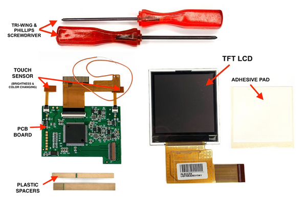
STEP 1: Remove the 6 tri-wing screws with a Y2 tri-wing screwdriver. DO NOT THROW AWAY SCREWS.

STEP 2: Remove backplate and you will see 2-3 screws holding down the motherboard. With a 00 Phillips screwdriver remove them and put them to the side.
NOTE: You should have 6 long screws and 2-3 short ones. DO NOT toss them as you will need them. The replacement screws are only meant for any lost/stripped screws.


STEP 3: Now you will remove the motherboard from the shell and screen. GENTLY lift the tabs on the top of the ribbon connector up. You can do this with the tip of your screwdriver or your finger. Make sure not to push too hard or it can break.

STEP 4: Lift up the ribbon and remove it from the adapter. You can remove the motherboard from the system. This is the only part you will need from the original GBP.

STEP 5: Prepare your shell on a soft surface to avoid scratches and attach an adhesive pad around the inner LCD frame.

STEP 6: Remove the white protective paper on the adhesive and place the NEW LCD on top The screen will be smaller than the old LCD so you might see a little space on the side.

STEP 7: To hold the screen in place, you will need to install the plastic spacers as shown in the picture. Also, place the insulating film on the back of the LCD.

STEP 8: Install both button and rubber pads and make sure no extra plastic interferes when the button is pushed down.


STEP 9: Plug LCD ribbon onto the port on the motherboard. To install GENTLY lift up the tab of the port and slide the ribbon dark brown side facing up. Once inserted flip the tab down to secure the ribbon.
*Make sure the ribbon is installed correctly. Many issues will be because the ribbon is not installed properly or it moves during installation*

STEP 10: Flip the small motherboard over and position the touch sensors at the positions shown in the picture. And place the larger GBP motherboard over.


STEP 11: Plug top ribbon into the GBP motherboard. And push the side tabs down to secure the ribbon into the port.

STEP 12: Solder the wire from the PCB Board onto the motherboard at the point below the power switch as shown in the picture.

STEP 12: Screw in the 2-3 Phillips screws back in and place the top power switch. Make sure the screws are not too tight. It can cause small white dots on the LCD or damage the board if screwed in too tight. Then place the back shell on the system.

STEP 13: Test the system. Always test your system before you close it. Any issues that arise can be fixed now. Als, test all the buttons the brightness switch, and color-changing mode. It should work by tapping on the IR sensor cap and have multiple brightness modes.

STEP 14: To close the system, screw in the 6 Tri-wing screws and install the glass lens.

Make sure to not tighten the screws too tight to avoid anything breaking or warping the shell.
Make sure to clean the lens and LCD screen well with a microfiber cloth to avoid any dust settling.
If you have any questions please email us at: sales@godofgamingshop.com